An industrial air pollution source |
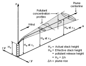
Visualization of a Gaussian pollution plume
|
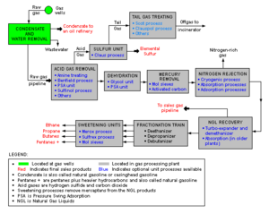
Schematic flow diagram of a natural gas processing plant |
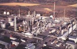
A natural gas processing plant
|
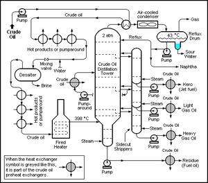
Schematic flow diagram of a crude oil distillation unit |
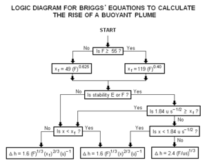
Logic diagram for using Briggs's plume rise equations
|

Tosco refinery in Northern California |
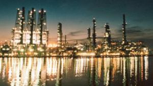
Chevron Oil's refinery in Pascagoula, Mississippi
|

EPA logo |
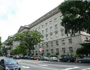
EPA Building in Washington, DC
|
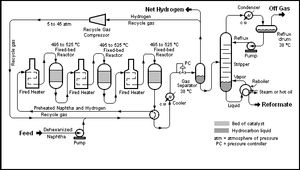
Schematic flow diagram of a typical semi-regenerative catalytic reformer unit in a petroleum refinery |
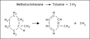
Diagram of chemical equation for converting methylcyclohexane to toluene and hydrogen
|
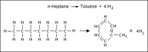
Diagram of chemical equation for converting
n-heptane to toluene and hydrogen |

Diagram of chemical equation for converting
n-octane to 2,5-dimethylhexane
|

Diagram of chemical equation for converting
n-heptane and hydrogen into isopentane and ethane |

NOAA's Logo
|
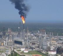
Motiva Refinery west of New Orleans |

ARL Headquarters Location
|
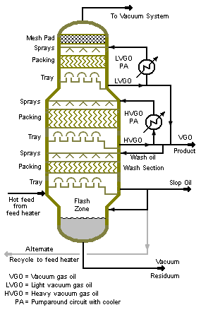
Diagram of a large-scale vacuum distillation column |
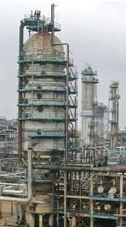
Large-scale vacuum distillation column used in petroleum refineries
|

ARL Logo |
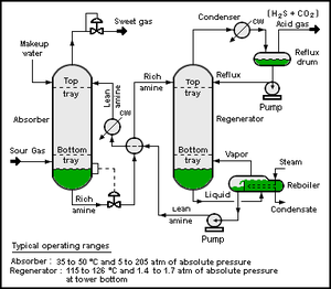
Schematic flow diagram of a typical amine gas treating unit
|
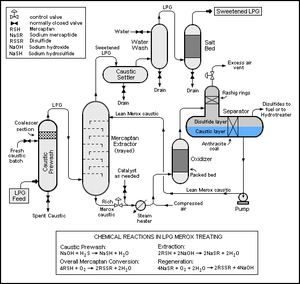
Conventional Merox unit for extracting mercaptans from LPG |
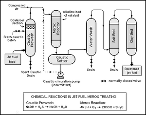
Conventional Merox unit for sweetening jet fuel or kerosene
|
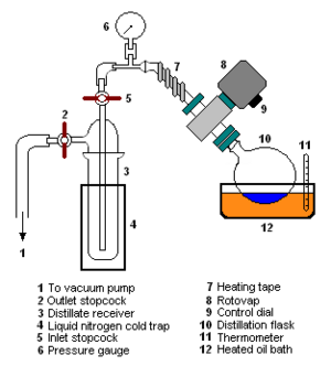
Rotary evaporation laboratory apparatus setup |

Vapor-Liquid Separator
|
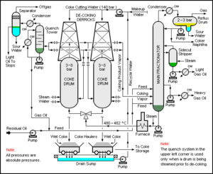
A typical delayed coking unit |
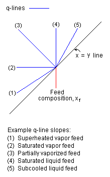
Examples of Q-line slopes
|
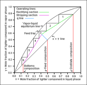
An example McCabe-Thiele diagram |
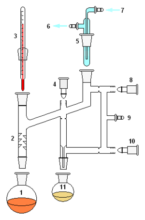
Perkin Triangle Distillation Setup
|
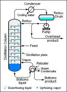
Large-scale, simple industrial distillation column |
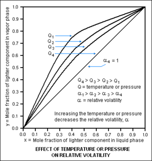
Effect of temperature and pressure on relative volatility
|
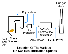
Location of FGD options |
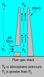
Outside and inside pressure difference causes draft in a flue gas stack
|

Four Corners Power Plant in New Mexico |
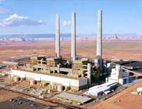
Navajo Generating Station in Arizona
|
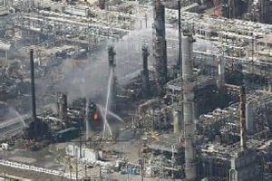
Fire and explosion damage at BP refinery (Texas) in 2005 |

Steam-Methane Reformer used in ammonia production
|

The thermodynamic cycle for vapor-compression refrigeration |
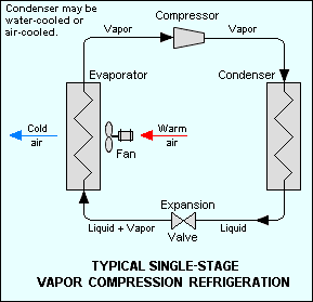
Schematic diagram of vapor-compression refrigeration system
|

Fan-induced draft counterflow cooling tower |

A fan-induced draft crossflow cooling tower
|

Power plant hyperboloid cooling towers (note water vapor plumes) |
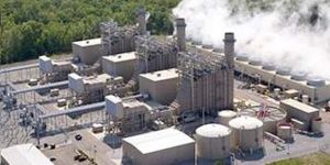
Power plant counterflow cooling tower (note water vapor plumes)
|
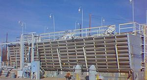
Process plant crossflow cooling tower |
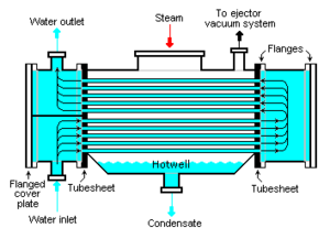
Schematic diagram of a typical water-cooled surface condenser
|

Schematic diagram of a typical injector or ejector |
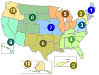
Map of the U.S. EPA Regions
|
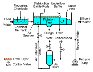
Dissolved air flotation unit |

Example graphs of gas compressibility factors
|

Example of a generalized compressibility factor graph |

Trickle filters in water and waste treatment unit, Christchurch, New Zealand
|
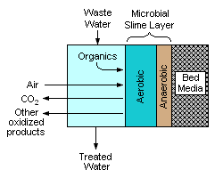
Schematic cross-section of the contact face of the media used in a trickle filter |
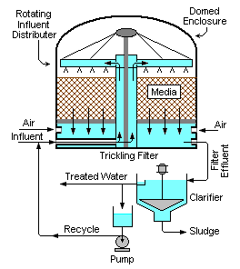
Schematic diagram of a complete trickle filter system
|
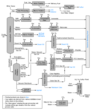
Schematic Flow Diagram of a typical petroleum refinery |
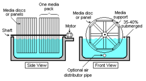
Schematic diagram of a rotating biological contactor
|
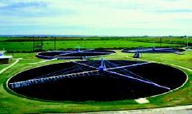
Large, shallow ground-level trickle filters in a municipal wastewater treatment plant |

Trickle filter in wastewater treatment plant, Littleton-Englewood, Colorado
|

Fluid Catalytic Cracker at Memphis, Tennessee Refinery of Valero Energy Corporation |
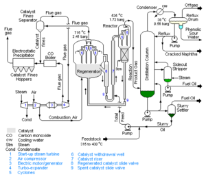
Schematic diagram of a fluid catalytic cracker
|
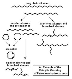
Diagrammatic example of the catalytic cracking of petroleum hydrocarbons |
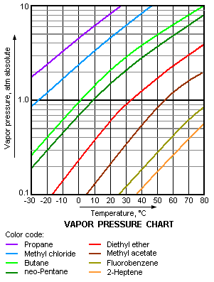
A typical vapor pressure chart of various liquids
|
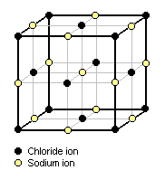
Cubic lattice structure of crystalline sodium chloride |
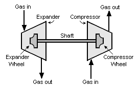
Schematic diagram of an expansion turbine driving a compressor
|
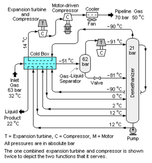
Schematic diagram of a demethanizer extracting hydrocarbon liquids from natural gas |
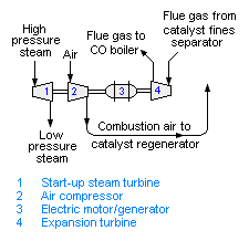
A schematic diagram of the power recovery system in a fluid catalytic cracking unit
|
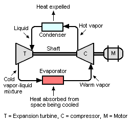
Schematic diagram of a refrigeration system using an expansion turbine and a compressor |
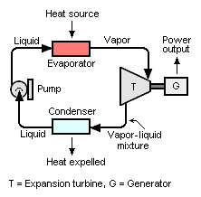
Generating electrical power by using an expansion turbine
|
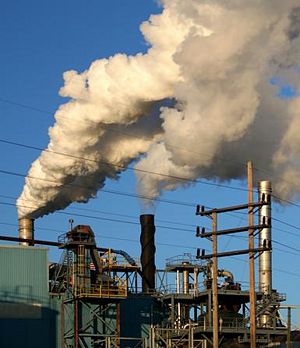
An industrial air pollution plume |
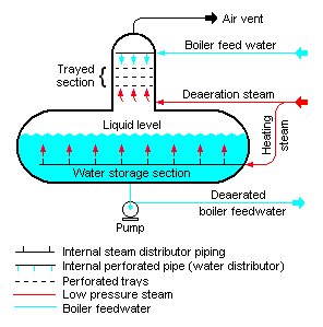
Schematic diagram of a Tray-type boiler feedwater deaerator
|

Schematic diagram of a Spray-type boiler feedwater deaerator |
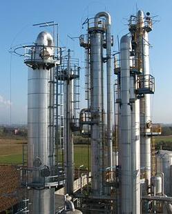
Industrial distillation columns
|
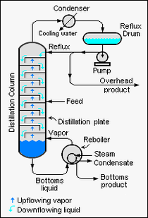
Schematic diagram of a binary distillation column |
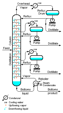
Schematic diagram of a multi-component fractional distillation column
|
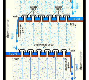
Trays in an industrial distillation column |
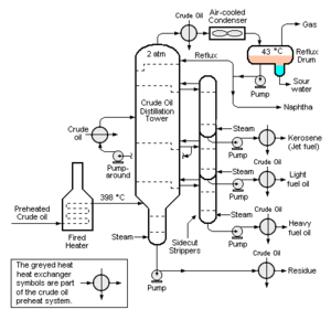
Schematic diagram of a crude oil distillation column
|
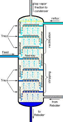
Bubble-cap trays in a distillation column |
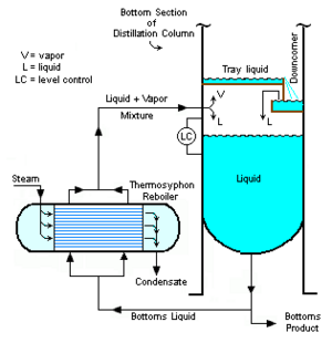
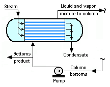
A typical steam-heated, horizontal thermosyphon reboiler used for heating distillation columns
|
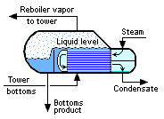
A typical steam-heated kettle reboiler used for heating industrial distillation columns |
A typical steam-heated forced circulation exchanger used for heating a distillation column
|


